New challenge. Some time ago I got installed a new garage gate, managed by a Sommer controller. The board has open pins for an additional opener, like an external button. So, other than the provided remote I had the chance to buy a second one or a wired/wireless pinpad for something around 80€.
But why doing something so easy and (…) cheap rather than spend a lot more money (well, maybe not this) and time to build an interface myself using a Raspberry?
So I started digging the hole of Home Assistant!
I started searching for generic stuff for Raspberry and garage door controller, and I immediately ran into Andews Hilliday project.
Before I could start buying stuff a friend of mine came up with an I/O board for Raspberry he had read about, and immediately started soldering this board with I2C, and Input and Output interfaces.
In the meantime I started investigating into Home Assistant and happily found a module (cover) already handling on its own the garage door natively. Gotcha!
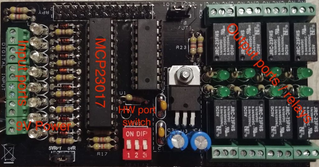
All my happiness vanished when I received the soldered board: it didn’t use the Raspberry bundled GPIO but, after some digging, I found it had this insane chip called MCP23017. I’m not really fond of electronic…
Looking around I discovered a Home Asistant dedicated component for this chip, but as a totally newbie to both HA and electronics I had hard time figuring out how to get it working.
So I’m summing up here the steps I did to control inputs and output of the MCP23017 with Home Assistant
First thing: i2c is not enabled by default in Raspbian. You can easily enable it by running
sudo raspi-config
And entering 5 Interfacing Options > P5 I2C > Enable. If you have problems you can check the steps at this page.
You can still install some command line tools help debugging and learning how to deal with the interface.
apt -y install i2c-tools libi2c-dev python-smbus
I’m not sure if you need to reboot the Pi after enabling it. Anyway to check if I2C is correctly enabled and connected just run:
sudo i2cdetect -y 1
(if you get no output or have an older RPi try replacing 1 with 0).
It should print out a summary of the i2c ports detected, like this:
     0  1  2  3  4  5  6  7  8  9  a  b  c  d  e  f
 00:          -- -- -- -- -- -- -- -- -- -- -- -- --
 10: -- -- -- -- -- -- -- -- -- -- -- -- -- -- -- --
 20: -- -- -- -- -- -- -- 27 -- -- -- -- -- -- -- --
 30: -- -- -- -- -- -- -- -- -- -- -- -- -- -- -- --
 40: -- -- -- -- -- -- -- -- -- -- -- -- -- -- -- --
 50: -- -- -- -- -- -- -- -- -- -- -- -- -- -- -- --
 60: -- -- -- -- -- -- -- -- -- -- -- -- -- -- -- --
 70: -- -- -- -- -- -- -- --
This means the program detected an i2c device on port 0x27. Take note of your output because this port must always be indicated when configuring sensors and switches in Home Assistant!
The chip default is 0x20, but it can be customized by using hardware switches. On my board I have three red switches to control the address.
Now the hardest part began, at least for me. How to control the relays and read input status?
I first tried a command line approach. After a lot of search I ran into raspberrypi-spy.co.uk which has few nice examples on configuration and could give some feedback on the board. Unfortunately the only commands which helped were the first tw:
sudo i2cset -y 1 0x20 0x00 0x80
sudo i2cset -y 1 0x20 0x14 0x01
These will set up the board and enable the first relay. So the board works! The site will go on in programming it via Python, but I didn’t want to go low level and study addressing.
Next challenge is to understand numerical to physical assignments.
The component page says:
The pin numbers are from 0 to 15 where: 0-7 correspond to port A (A1-A8) and 8-15 to port B (B1-B8).
Unfortunately this doesn’t explain which one is input and which output. Product page says any port can be any of the two.
The examples in the page use pins 0-7 for input (binary_sensor) and 8-15 for output (switch). In both components in the pins section it says you can use any id from 0 to 15.
It probably depends on the wiring!
In my case I had pins 0-7 for switches (relays) and 8-15 for sensors.
So to get which ones where what I added this to configuration.yml:
binary_sensor:
  - platform: mcp23017
    i2c_address: 0x27
    invert_logic: true
    scan_interval: 2
    pins:
      8: garage_door_8
      9: garage_door_9
      10: garage_door_10
      11: garage_door_11
      12: garage_door_12
      13: garage_door_13
      14: garage_door_14
      15: garage_door_15
and so I was able to figure out which pin to use for my door sensor. Similarly I did the same for switch, and managed to get together this config:
binary_sensor:
  - platform: mcp23017
    i2c_address: 0x27
    invert_logic: true
    scan_interval: 2
    pins:
      15: garage_door_15

switch:
  - platform: mcp23017
    i2c_address: 0x27
    pins:
      0: Garage Switch
Controlling the Sommer automation with Raspberry

The gate controller – outside 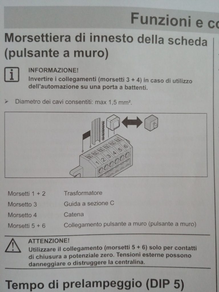
Sommer gate pins explaination
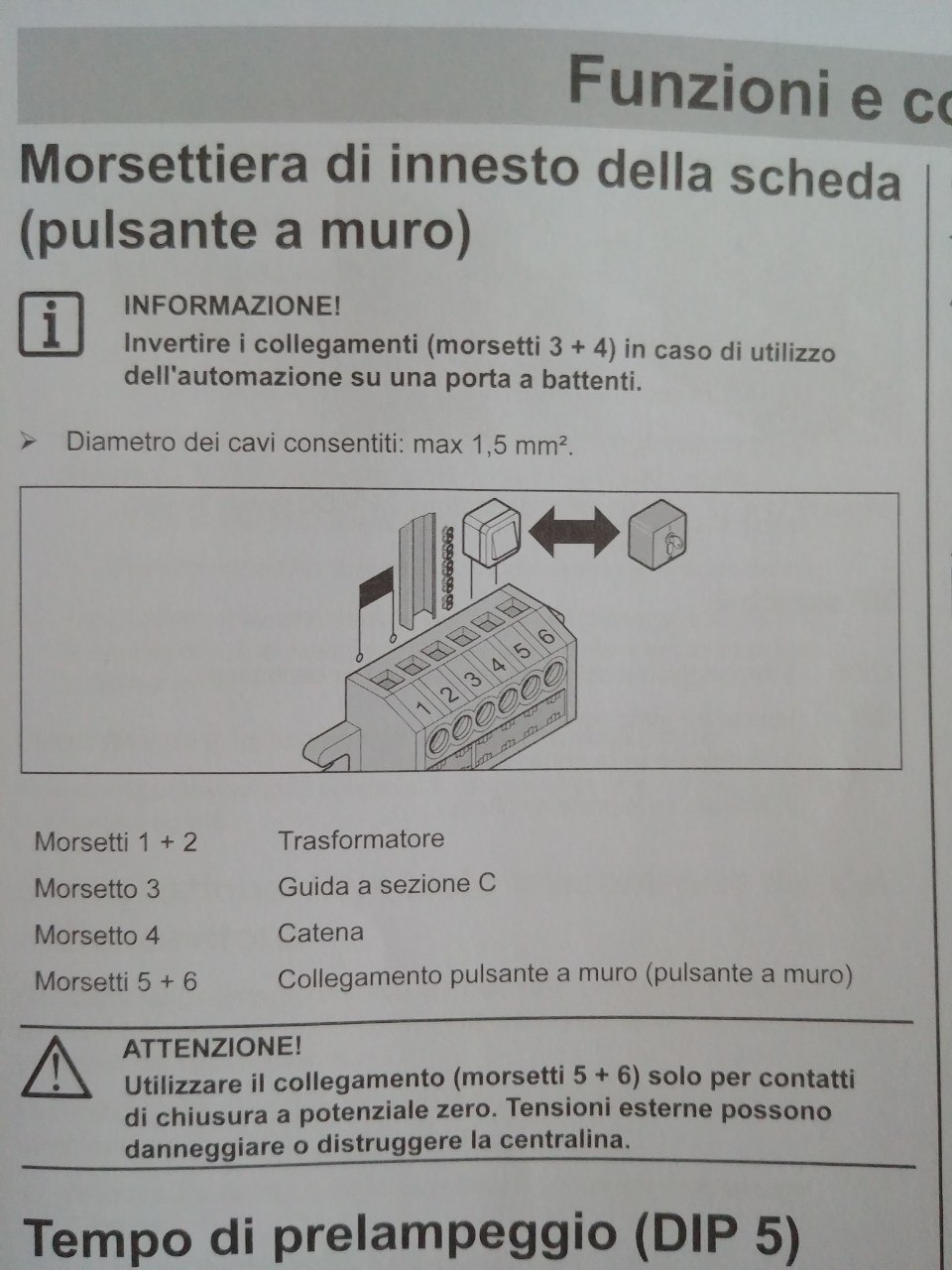
My garage door controller by Sommer is very simple: just one button. That button triggers the engine. If it’s stopped it moves, and the other way around. Every restart moves in the opposite direction. It’s a push button and not a switch one, this means you cannot really control open/close.
To emulate the button they make available two pins on the board, 5 and 6 on the instructions above. Those pins must be just closed, no tension (C and NO on the I2C board above).
Given that the above config could have been enough in Home Assistant: just trigger the switch and see the status of the gate on the sensor.
But the switch is either On or Off, once the relay is triggered it must also be stopped. Here it comes Home Assistant scripting!
From the Lovelace UI > Settings > Script and create a new one. The scripts.yaml is very simple:
'1566942782554':
  alias: Bottone garage
  sequence:
  - data:
      entity_id: switch.garage_switch
    service: switch.turn_on
  - delay:
      milliseconds: 100
  - data:
      entity_id: switch.garage_switch
    service: switch.turn_off
That is turn the switch on, wait 100ms, turn it off again. Worked immediately like a charm!
This could just have been enough to control the garage door. The UI already populates with the sensor, the script and the switch. But it would be nicer to use the cover component of HA, which gathers both of the two. But that uses the native gpio pins of Raspberry, not the i2c.
Using the Template Cover component
HA has an (almost) infinte set of resources. Even for handling cover there are several ways, the other one is the Template Cover which allows you to manage it with custom components.
Wrap it up and get something like this:
cover:
  - platform: template
    covers:
      garage_door:
        friendly_name: "Garage Door tpl"
        value_template: "{{ states('binary_sensor.garage_door_15') == 'off' }}"
        stop_cover:
          service: script.1566942782554
        open_cover:
          service: script.1566942782554
        close_cover:
          service: script.1566942782554
So I’ve created a Garage Door tpl element that behaves like a cover but runs custom command/components to manage the door. The state is obtained from an evaluation and control is done by a script.
Of course as said above since it’s not a switch all the actions execute the same script, and not really what they’re meant for. But the nice thing is to have up/down buttons enabled based on the state of the gate.
In order to manage the door from the clouds of everywhere I had to connect to the home LAN. Luckily with a pair of power line adapters I was able to make it easily, despite the big footprint.

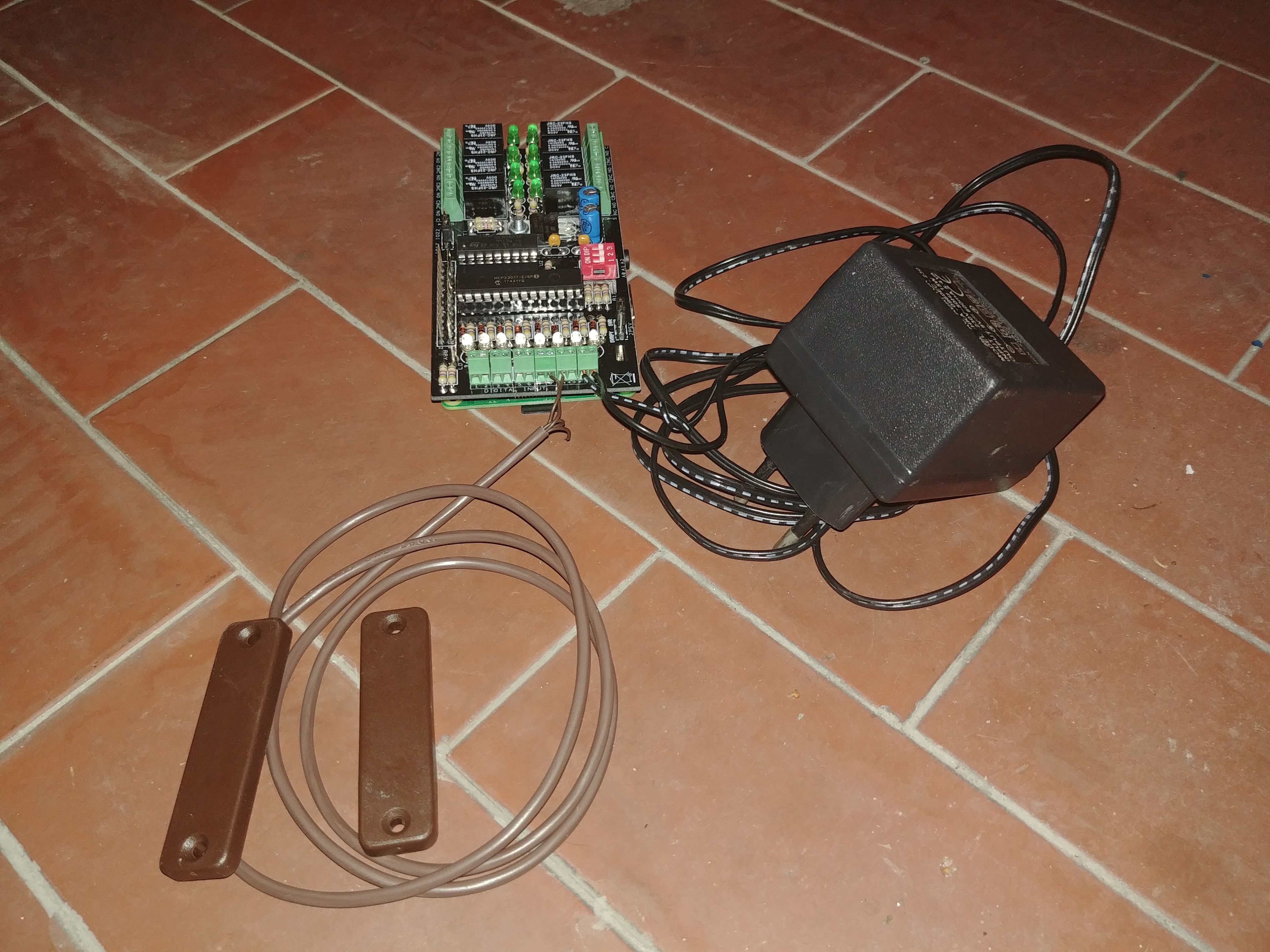
All the components together 
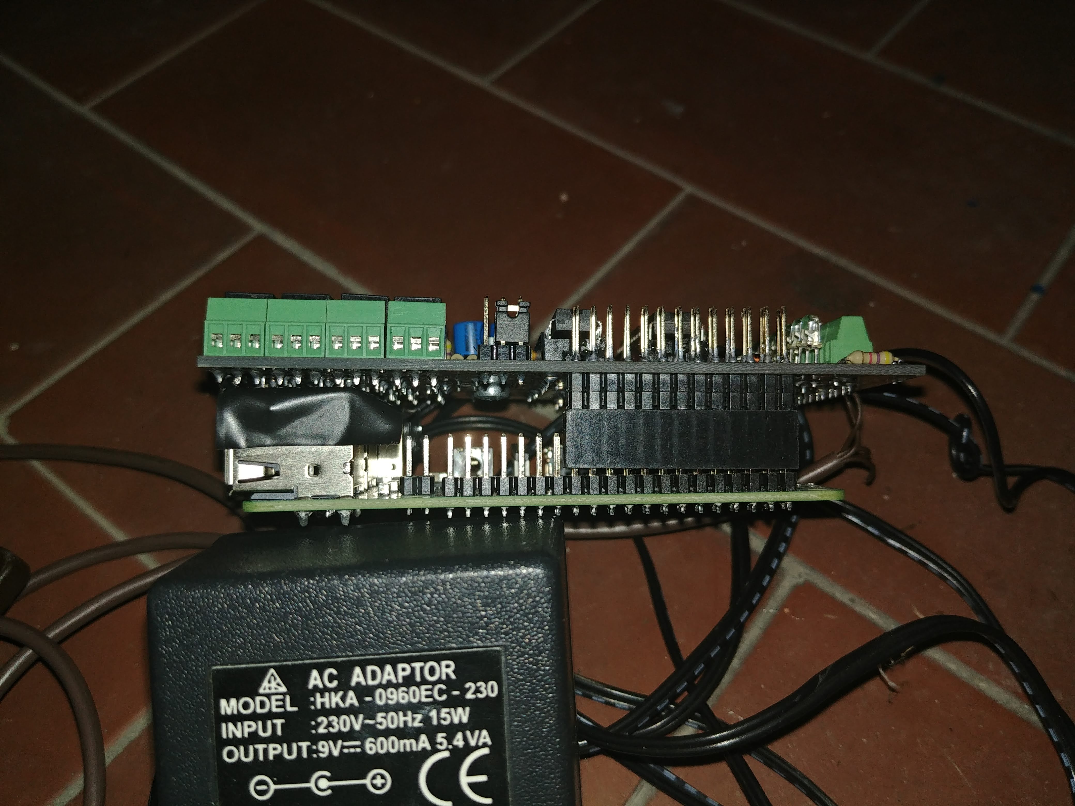
Side of the Raspberry + I2C expansion board 
Mounted magnetic door sensor 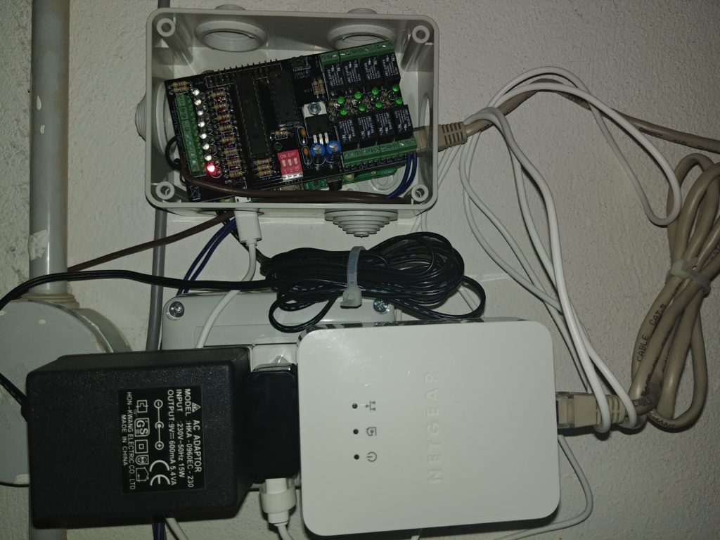
All the stuff mounted up on the wall.
Wiring not final 🙂